AC Induction Motor KG-18075M22 AC220V/50Hz Used In Commercial
Kitchen Equipment
Overview
Essential details
Warranty:3years
Place of Origin:Guangdong, China
Brand Name:Go-Gold
Model Number:KG-18075M22
Type:Induction Motor
Frequency:50/60HZ
Phase:Three-phase
Protect Feature:Drip-proof
AC Voltage:220v
Efficiency:IE 2
Name:KG-18075M22
KG-18075M22 Commercial Kitchen Equipment AC220V/50Hz 4P NoLoad
Power 2500±10% Three Phase
Performances specification
VOLTAGE
(V) | CURRENT
(I) | POWER
(W) | SPEED
(RPM) |
3P
AC220V/50HZ | 9.4±10% | 2500±10% | 1400±100 |
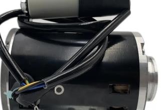
Outer dimensions

Induction motor refers to a type of motor that uses electromagnetic
induction between the stator and rotor to induce current within the
rotor to achieve electromechanical energy conversion.
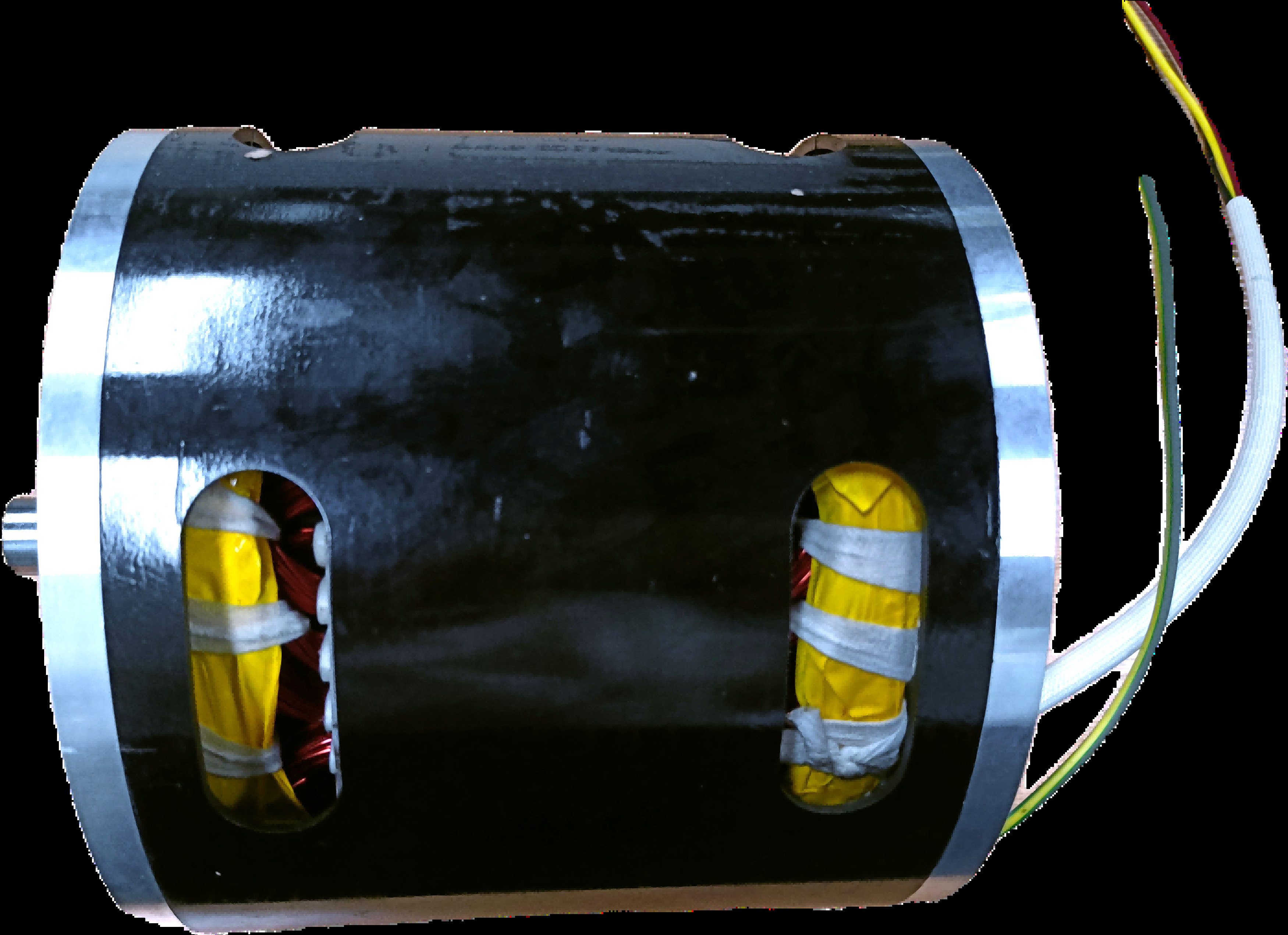
The stator of an induction motor consists of three parts: the
stator core, stator winding, and frame.
The rotor is composed of a rotor core, rotor winding, and shaft.
The rotor core is also a part of the main magnetic circuit, usually
composed of 0.5mm thick silicon steel sheets stacked together, and
the core is fixed on the shaft or rotor bracket. The outer surface
of the entire rotor is cylindrical. The rotor winding is divided
into two types: cage type and winding type.
Under normal circumstances, the rotor speed of an induction motor
is always slightly lower or slightly higher than the speed of the
rotating magnetic field (synchronous speed), so an induction motor
is also known as an "asynchronous motor".
When the load of an induction motor changes, the speed and slip of
the rotor will change accordingly, causing corresponding changes in
the electromotive force, current, and electromagnetic torque in the
rotor conductor to meet the needs of the load.
According to the sum of the positive and negative slip rates,
induction motors have three operating states: electric motor,
generator, and electromagnetic braking.
The rotating magnetic field
The basic idea of an electric motor is to generate two magnetic
fields: rotor magnetic field and stator magnetic field and make the
stator field rotating. The rotor will constantly be turning to
align its magnetic field with that of the stator field.
The 3-phase set of currents, each of equal magnitude and with a
phase difference of 120o , flow in the stator windings and generate
a rotating field will constant magnitude.
The stator of an induction motor consists of three parts: the
stator core, stator winding, and frame. The stator core is a part
of the main magnetic circuit. In order to reduce the eddy currents
and hysteresis losses generated by the excitation current and
rotating magnetic field in the iron core, the iron core is stacked
with 0.5mm thick silicon steel sheets. For motors with larger
capacity, both sides of the silicon steel sheet are coated with
insulation paint as interlayer insulation. The small stator core is
stacked and compressed into a whole with silicon steel sheets, and
then fixed in the frame; Medium and large stator cores are
assembled by fan-shaped punching pieces.
There are many slots with the same shape uniformly punched in the
inner circle of the stator core to embed the stator winding. Small
induction motors typically use a semi closed slot and a single
layer (loose down) winding made of high-strength enameled wire,
with slot insulation between the coil and the iron core. A semi
closed slot can reduce the magnetic resistance of the main magnetic
circuit and reduce the excitation current, but embedding wires is
less convenient. Medium induction motors typically use half open
slots. Large high-voltage induction motors all use open slots for
easy wire insertion. In order to achieve good electromagnetic
performance, both medium and large induction motors use
double-layer short pitch windings.
The rotor is composed of a rotor core, rotor winding, and shaft.
The rotor core is also a part of the main magnetic circuit, usually
composed of 0.5mm thick silicon steel sheets stacked together, and
the core is fixed on the shaft or rotor bracket. The outer surface
of the entire rotor is cylindrical. The rotor winding is divided
into two types: cage type and winding type Cage rotor.
A cage winding is a self closing winding composed of guide bars
inserted into each rotor slot and ring end rings at both ends. If
the iron core is removed, the entire winding is shaped like a
"circular cage", hence it is called a cage winding. To save copper
and improve productivity, small cage motors generally use cast
aluminum rotors; For medium and large motors, due to the difficulty
in ensuring the quality of cast aluminum, a structure of inserting
copper bars into the rotor slot and welding end rings at both ends
is adopted. The cage type induction motor has a simple structure
and convenient manufacturing, making it an economical and durable
motor. So it has a wide range of applications.
Wound rotor.
A three-phase winding composed of insulated wires embedded in the
slot of a wound rotor, with the three outgoing terminals of the
winding connected.
It is connected to three Slip ring on the rotating shaft, and then
led out through the brush. This rotor is characterized by that
external resistance can be connected in the rotor winding to
improve the starting and speed regulating performance of the motor.
Compared with cage rotor, wound rotor has a slightly complex
structure and is slightly more expensive, so it is only used in
situations where low starting current, high starting torque, or
dispatch is required